Optimized Planet Generation
The process consists of two parts:
1- Creating shared assets
2- Customizing planets
CREATING SHARED ASSETS
1 - Base Sphere Mesh
First thing we need is a sphere mesh. For this we are going to use a quad-sphere so the geographical distortions are on a uniform scale across the surface. This can be done by normalizing each vertex vector on a cube mesh and spreading the vertices equidistantly by the following equation.
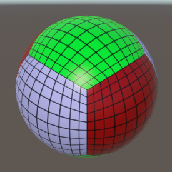

See https://catlikecoding.com/unity/tutorials/cube-sphere/ for a detailed explanation.
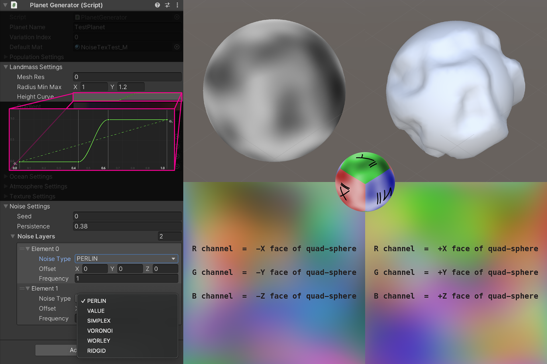
As for the UVs of the mesh, we will have two maps. The first will be used for determining the cube-face index and thus which texture channel to sample from. The second will be used for sampling the textures, it will have all faces coinciding. This technique will enable us to store noise data for all faces with only two RGB textures and without wasting pixels.

This sphere is our most basic building block for any planet.
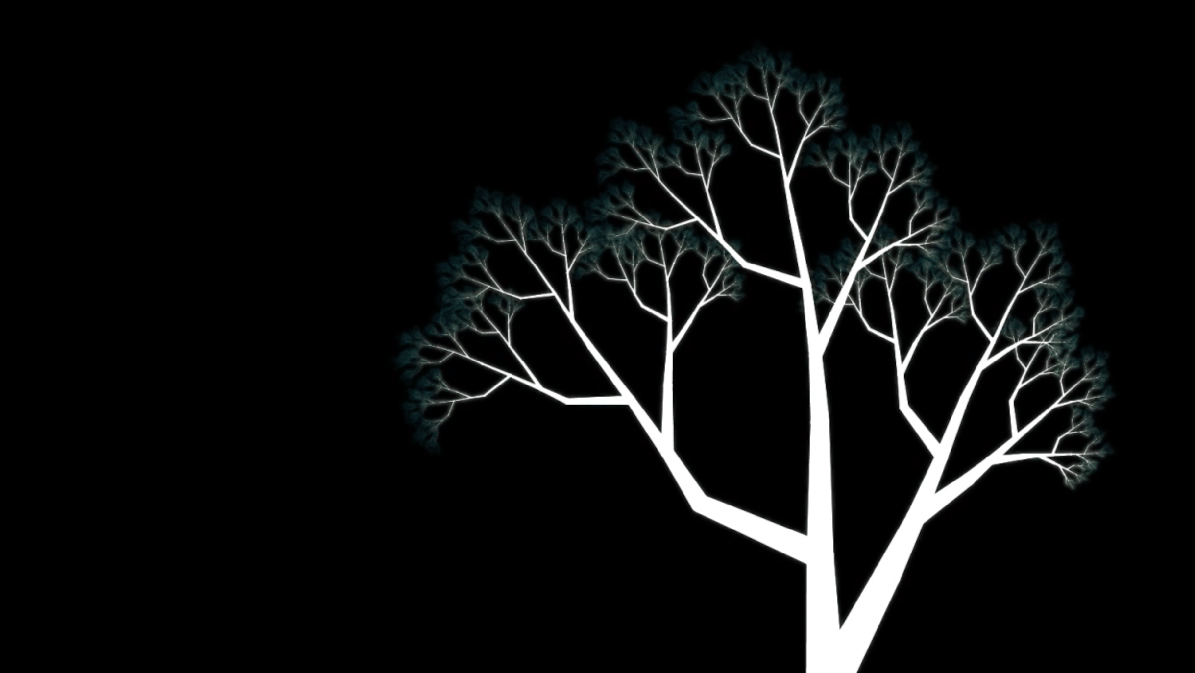
2 - Planet Primitives
A planet primitive consists of a geography mesh and two RGB noise textures.
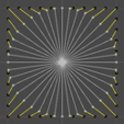
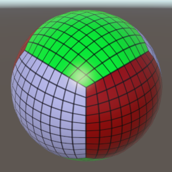
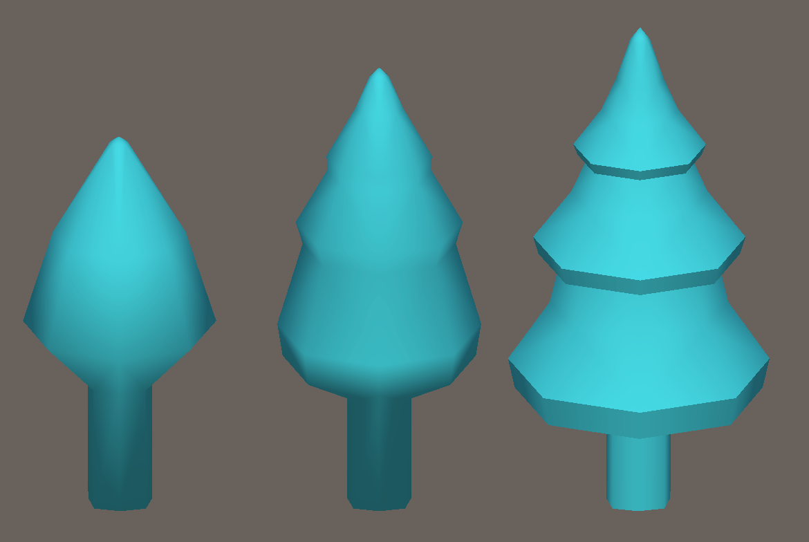
Now that we have our base sphere we can distort the mesh by sampling 3D noise at each vertex position and using the value to lerp between the maximum and minimum radius values. We can also use a height curve to remap the noise while deforming the mesh as can be seen on this example geography. We can use more noise layers with higher frequencies for a more realistic planet or other noise types like voronoi for more stylized planets.
We will also need to store this noise data as we will use it later for texturing and sampling 3D noise in realtime is expensive in terms of performance. Per vertex data will not be enough for texturing so we will sample the noise at a hypothetical vertex position for each pixel depending on our texture resolution. We can keep the resolution fairly high because we are using the efficient uv system described above and we will only store two RGB textures with no pixels wasted.
We do not need a unique primitive for each planet. We can generate 10 primitives and then create 10 unique variations for each resulting in a lot of variety. To demonstrate, we will only use this one primitive throughout the documentation.
3 - Shared Textures
We can use seamless normal map, roughness, occlusion map, etc. textures for detail. It will be useful to create such a library but this is optional. These textures can be found online or be generated. Substance designer is a good option.
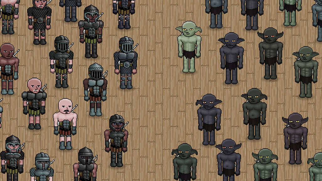
4 - Population Element Models
Below is an example model set. Two planets can share the same house set while using different tree sets but even for shared sets, we can achieve variation by using different materials. It is important to use a minimum number of materials per planet to keep the draw calls low so here is a very efficient method.
We do not need resolution for albedo textures as population elements will be very small on our screen even in this miniature scale planet we are making for this documentation. However the tool does allow that extra bit of detail by using shared normal maps. We need 3 UV maps on our models. Just like the UVs of our quad-sphere, UV0 will be used for determining which texture to sample from and UV1will be used for sampling the texture. UV2 is optional and can be used for sampling additional details like windows of this house. In fact not even UV1 is needed if we will not be using normal maps since UV0 will be enough for sampling our color and parameter value textures. These textures will be generated in the Customizing Planets part on a per planet basis, they won't be shared assets but it's important to plan their layout and adjust the UV system according to how they will be sampled.
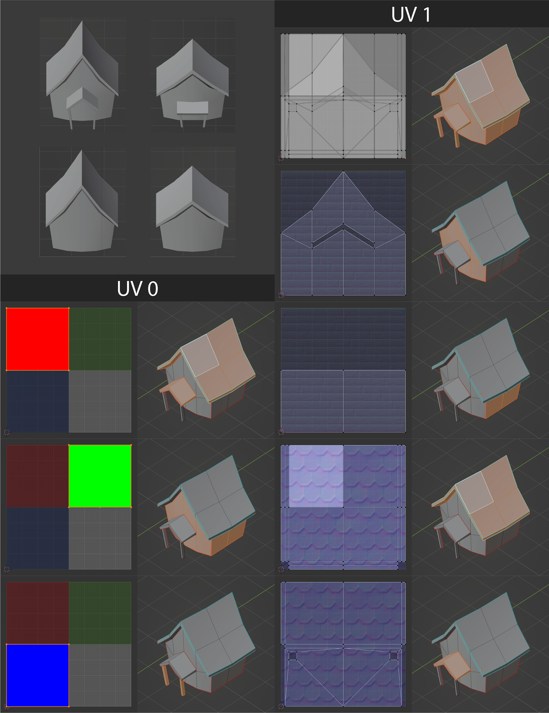
We would normally use different materials for the roof and walls of this house which would also require separating it into sub-meshes. With this technique we combine these materials into a singe material. We can also make a larger texture for UV0 such as 3x3, assign each pixel a "pseudo-material" such as metal, wood, stone, etc., and use the same material for all the population elements on a planet.
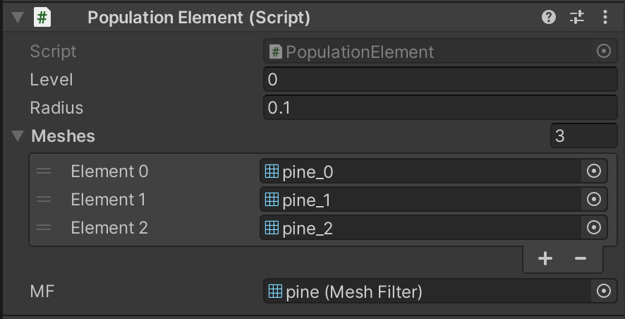
We will store these model sets as population element prefabs for later use. Each population element can have 1 or more meshes to randomly choose from. It also has a radius value which we will use for preventing the superimposition of elements.
5 - Shaders
We will have 4 shaders that are used by all planets. Landmass, Ocean, Atmosphere and Population. If we plan the population model UV's well, each planet will only be using 4 materials, however it is ok to use more than one material for the population elements.
CUSTOMIZING PLANETS
At this stage we have prepared all the assets we will use to create unique planets. Now we have to generate the data textures for planet materials and populate the planet.
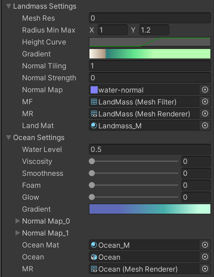
1 - Ocean and Landmass Materials
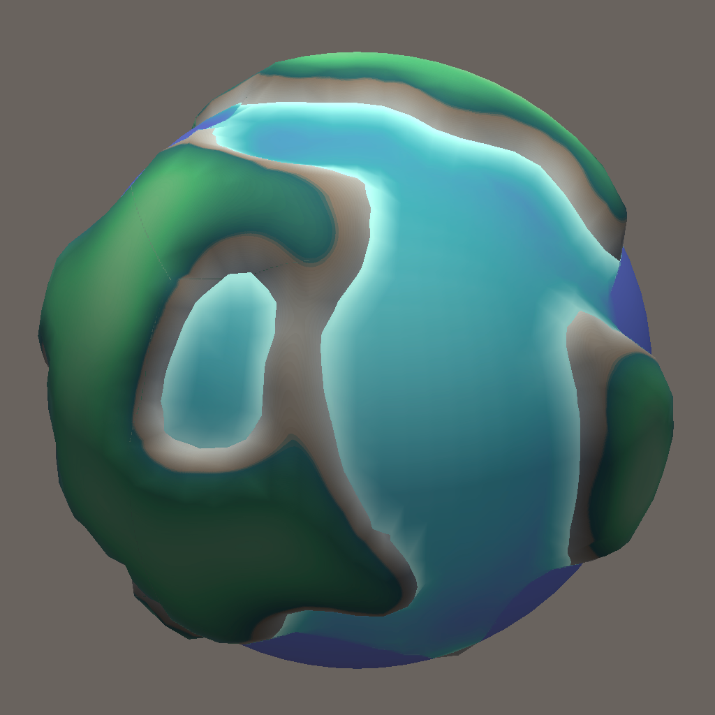
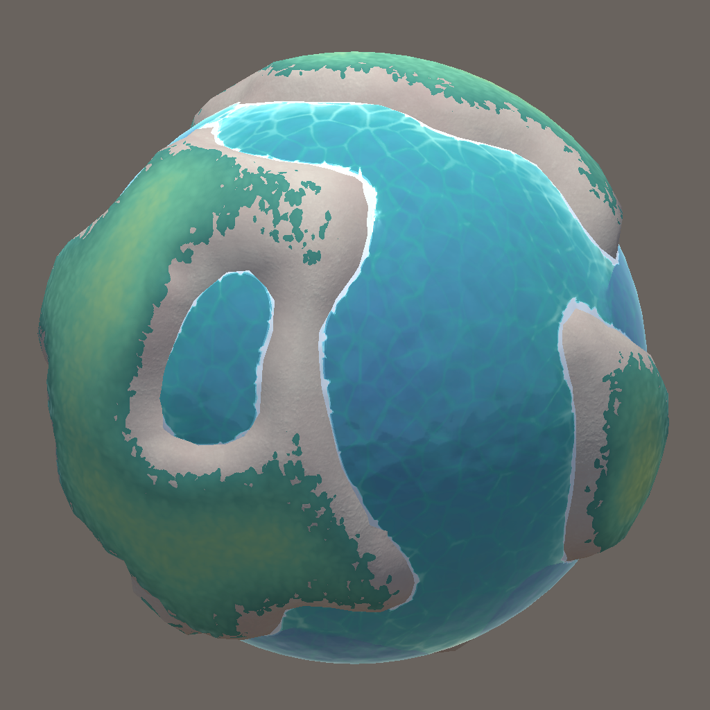
We will add another quad-sphere for oceans. This sphere will use a shader that reads the scene depth data. Changing the water level parameter between 0 and 1 will scale the sphere between the minimum and maximum radius values of our planet. The water level value will also be sent into the landmass shader for remapping the noise texture values to the shoreline. We will use the scaled noise gradient and the depth gradient seen in Figure-1 to respectively sample our landmass and ocean color gradients that are passed into the shaders as textures. We can use the data visible in Figure-1 in many interesting ways like blending between textures as can be seen in Figure-4. The tool is not designed for runtime manipulation of the water level so changing it will require adjustments in parameters such as foam and color gradients. What works for water level 0.5 may not look right for 0.1 or 0.9 as can be seen in Figure-5.
2 - Populating the Planet
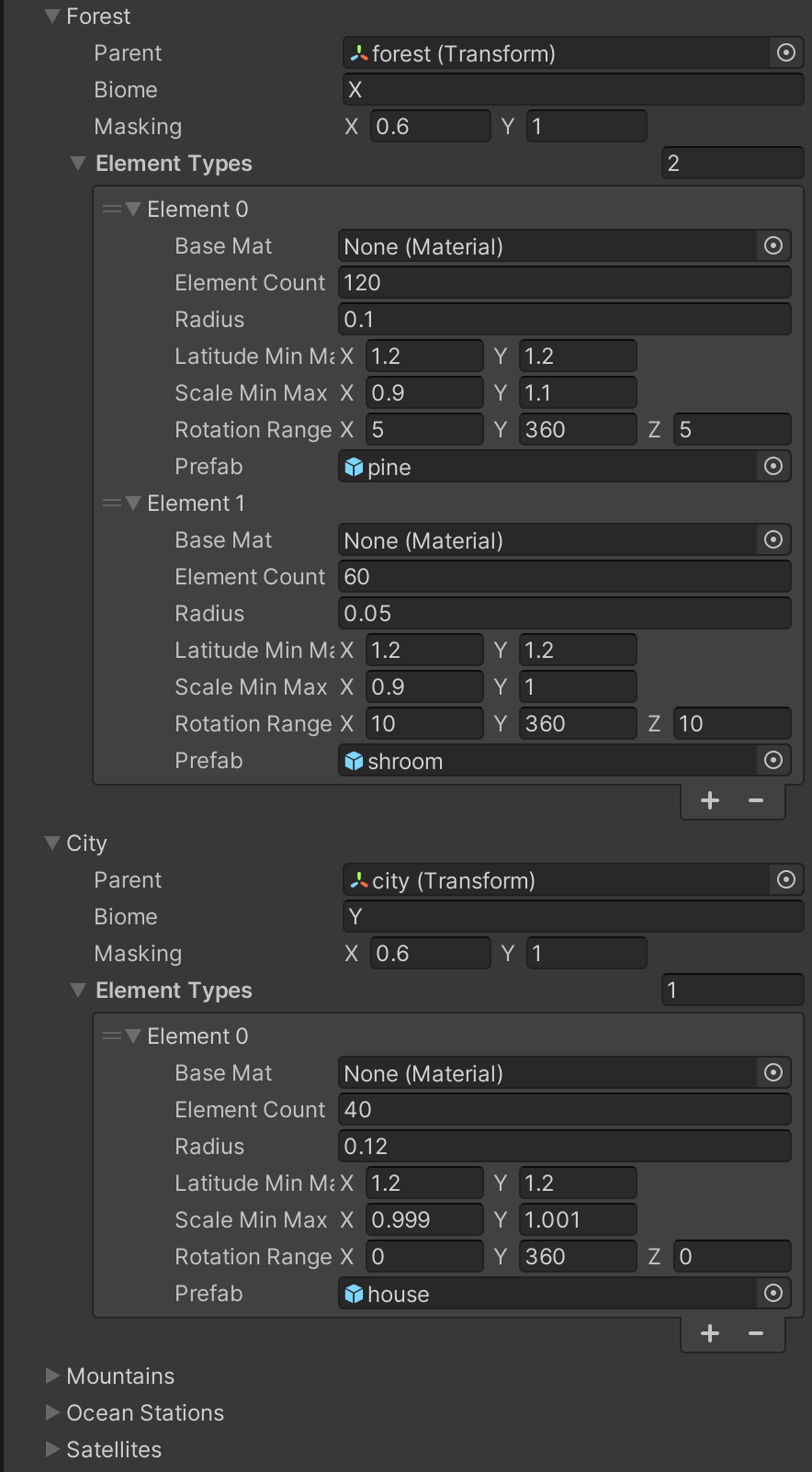
We can use any set of 3D models to populate the planet. Population settings include 5 population types (forest, city, satellites, ocean stations and mountains) that demonstrate the tools features and logic but more can be added if needed.
For each element type we can set a count. We can have the forest population consist mostly of pines and have less mushrooms. These numbers will not be exact because if the algorithm is unable to find a suitable position to place the 55th mushroom, there will be 54 mushrooms rather than 60 on the planet. Each element also has a transform range allowing variety in angle and scale. Latitude should usually be kept to the land radius for houses and ocean radius for boats. A range can be used for floating objects such as satellites.
There are 3 conditions an element must meet to be instantiated and placed. We pick a random position on the unit sphere, scale it to the elements latitude value and then check for these 3 conditions.
A) Noise Masking
We do not need to do this for the satellites so we set the masking range to 0 and 1. We want boats to only be placed in the ocean so we set the masking values of oceanStations to 0 and waterLevel - 0.1 just to make sure we don't place boats clipping into the land at shorelines. For any element type we want on land we do the opposite, waterLevel + 0.1 and 1.
B) Biome
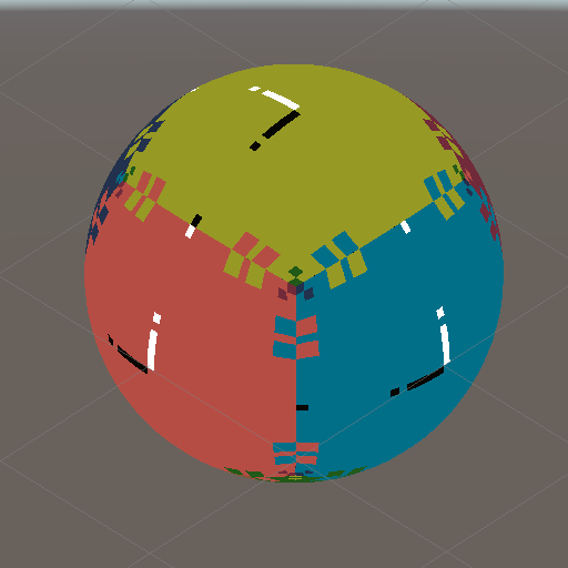
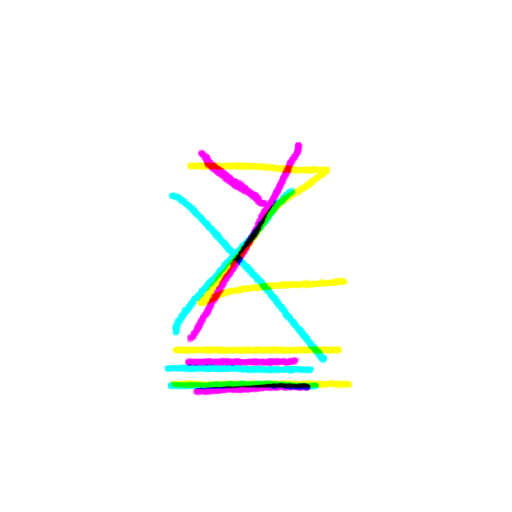
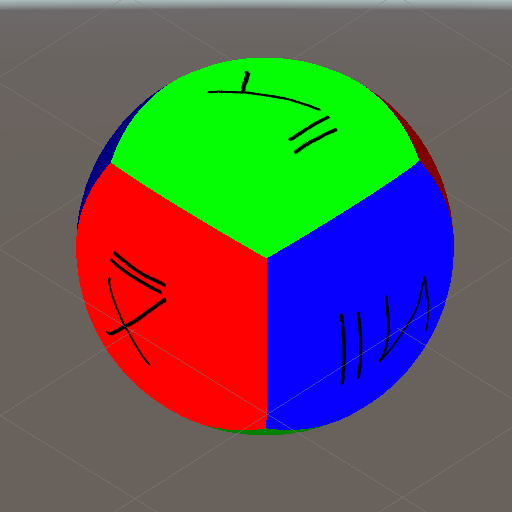
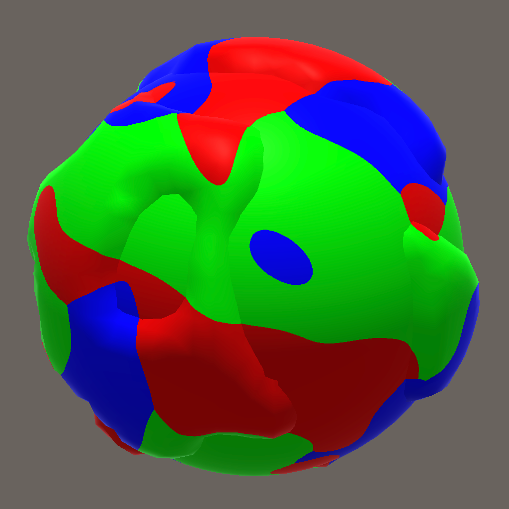
If we are going to have multiple element types populating the same noise value range and we want them to be grouped rather than distributed homogeneously, we need biomes. Figure-2 below is an example biome map created by generating 3 noise maps and comparing their values. The red areas are where the value of NoiseMapX is greater than of NoiseMapY and Z, green where Y is greater and blue where Z is greater.
In this example we do not need a biome for oceanStations since it is separated from other element types by Noise Masking so we set its biome to 0 and same goes for satellites. We can also do without biomes for land elements and they will be homogeneously distributed but if we want forest areas and settlement areas to be distinguishable, we can set the biome to X for city and Y for forest. This way houses will only be placed on the red areas and trees and forest elements will only be placed in the green areas. Pine trees and mushrooms will still be homogeneously distributed inside the green area since they belong to the same population type. We can assign Z to mountains or leave it empty for open areas as it is in Figure-3 below. A biome value of 0 will pass this test automatically.
C) Proximity
Finally if the random position we picked is in the right noise range and biome, we check if it is far enough from surrounding element to prevent clipping objects. An element passes this test if its distance to each surrounding element is greater than the sum of their radius values.
If a position passes all 3 conditions, a random mesh is selected form the list the element contains, and it is positioned, scaled and rotated by random values inside the elements value ranges.
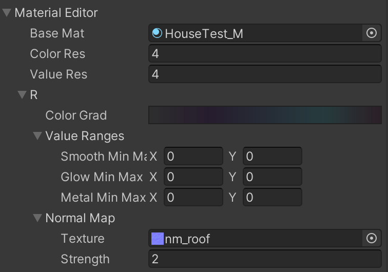
3 - Population Material Textures
Using the population shader we will create a population material for the planet. We can use more than one and assign them to population element prefabs. The planet generator tool contains a module for editing the population material and it is also responsible for baking parameters into textures and passing them to the material. R in Figure-1 is a pseudo material. The population material uses one color texture and one value texture that contain data for each pseudo-material. A separate normal map is needed for each pseudo material but using normal maps is optional. The color and value textures have x dimensions of colorRes and valueRes respectively. This resolution determines how many variations can be sampled from the color gradient and value ranges. The value texture contains smoothness, emission and metal values in its R G B channels respectively. The y dimensions of these textures are determined by the number of pseudo materials we use. UV0 is used for selecting the y coordinate to sample the textures, in other words it indexes a pseudo-material. The x coordinate is randomized per instance id to create variation, this is why we use gradients. If we want a pseudo material to have uniform color and values across all elements we can simply set the colorRes and valueRes parameters to 1 pixel.

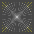
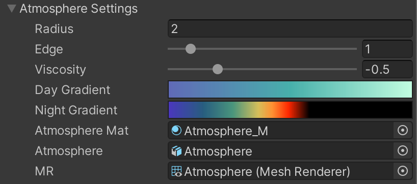
4 - Atmosphere
Atmosphere simulations usually us Rayleigh Scattering which is very expensive in terms of performance. We are going to achieve a similar look with a cheaper method. Just like the ocean we are going to use a scaleable quad-sphere that reads the depth texture (Figure-1). We will simulate the cast shadow of the planet by combining a sphere gradient and cylinder gradient based on the direction of the sun (Figure-2). We have a day gradient and night gradient that are passed to the shader as textures. We can also control the viscosity and edge sharpness of the atmosphere as can be seen in figures 3 and 4 respectively.
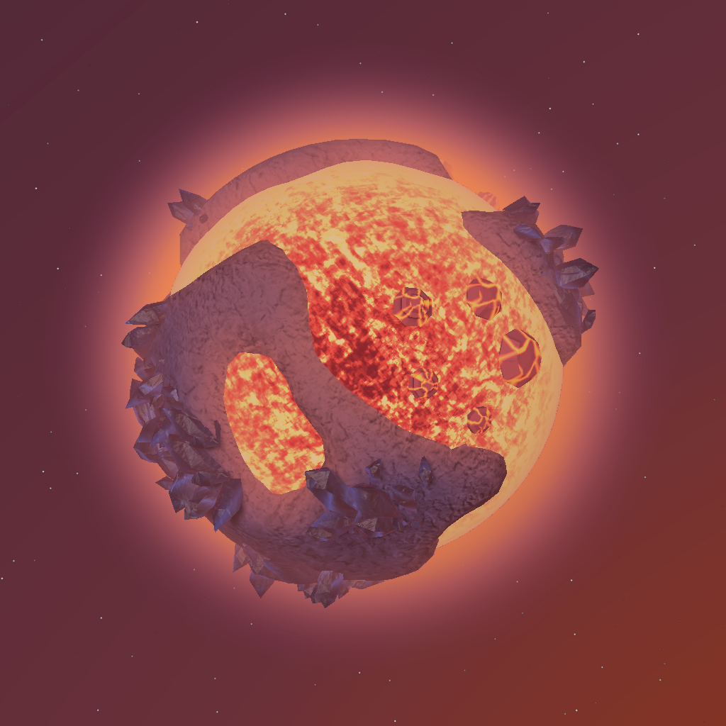
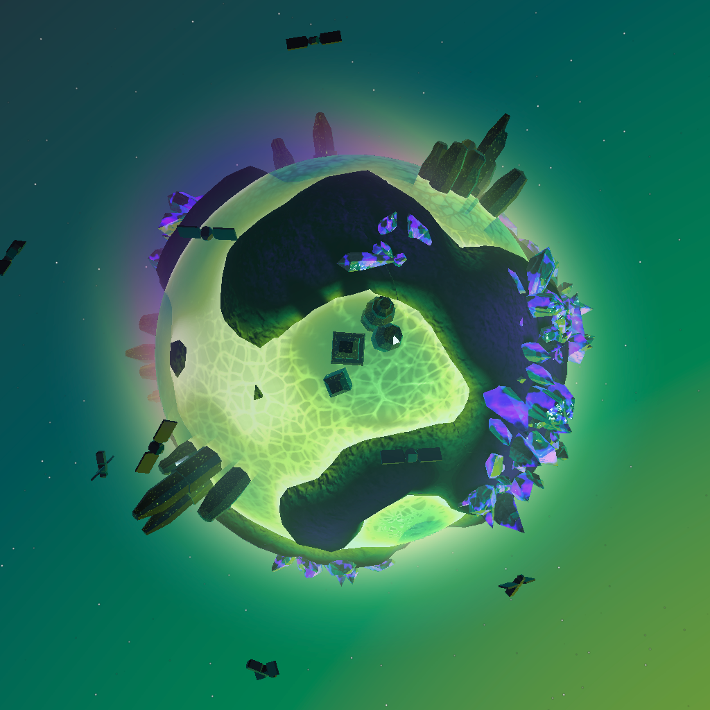
EXAMPLE PLANETS
With this tool we can create many planets fast and save them as prefabs.